Here is my first attempt at an "injection" type burner. Technically it's called the G6-IS1 which stands for "Generation 6 Injection Style 1" since it is my sixth generation of waste oil burner and the first of the injection type rather than the "box burner" like the G1-G5 designs. But since the name sounds more like a model of Lexus autos I've decided to give it a more "human" name. Therefore since it's shape is some what like a "T" or a "hammer shape" I decided to call it "Lio's hammer." That rolls off the tongue better than "Lio's T-shaped burner" and sounds more macho as well.
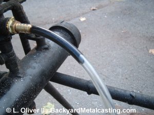
For the protoype burner I made the fuel line out of this clear vinyl tubing. Here you can see the used motor oil flowing through the line. I've since switched to a slightly larger fuel line. So 2-3 gallons of oil per hour can flow through the line when melting iron.
Those are two terms that I use to classsify the burners based on their method of igniting the oil. The "box burners" are the G1-G5 designs. They are basically metal boxes internally lined with refractory. The oil ignites and burns inside them and the resulting flames are blown into the furnace. Plenty of heat is produced but the burner itself absorbs a tremendous amount of it making the system less efficient. And the insides can get clogged with ash and oil residue like creosote. As if that weren't enough the refractory lining can melt and deform decreasing the effectiveness of the burner. Problems...
The "injection style" burner is like a fuel injector in a car engine. The oil is sprayed (injected) directly into the furnace as small droplets that burn mostly in the furnace chamber. Almost all of the heat is generated in the furnace. The burner is much more efficient, lighter and can be built in about an hour from scraps. There's basically no maintanance. Nice...! In truth since the oil is merely blow into the furnace and it burns there, the oil burner is not really a burner but rather an "oil injector."
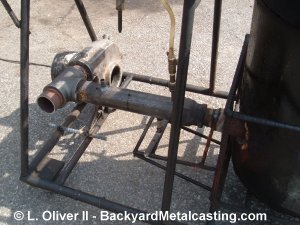
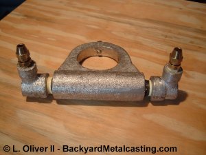
Here is a general overall view of the burner with what I call the "thermal transfer ring" on it. Basically it's a ring that fits over the burner's tip. The flame heats the tip and conducts the heat into the ring. At the top of the ring a pipe is cast within it and the oil moving through the pipe absorbs the heat. Waste heat put to good use. The front of the burner is resting on a brick because the base legs are un even. I retrofitted this burner to fit my current furnace framework which was designed for the previous burner designs.
Here is another overall view of the burner. The propane line is installed in this photo. The reason the blower is attached to a "T" fitting is because when I first tested the burner the blower pressure blew the propane flame out, and I used propane to warm up the furnace before I opened the oil line. So a "shutter" was put on the open end of the "T" for air regulation. I've sense learned that this "T" fitting is not neccesary with furnace use. Click photo for a larger view
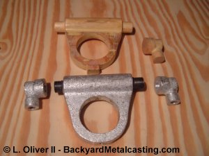
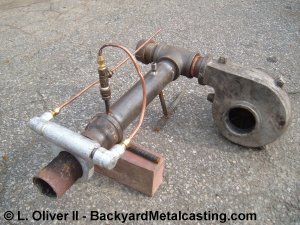
Here you can see the patterns for and the actual part I call the "thermal transfer ring." The pipe inside the casting is connected to the fuel lines and oil flows through it. The ring is installed on the flare pipe and as the flare pipe gets hot (it always does since it protrudes into the furnace) the heat is conducted into the ring and through the pipe to pre-heat the oil. So the oil is warmed by heat that would otherwise be lost.
Here is a view of the thermal blah... blah... blah.. assembled and ready for the oil lines and installation on the flare pipe. Notice the reducing elbows, I made those because otherwise I'd probably have to go to a plumbing supply specialty store to find them and pay an excessive price. The ring is aluminum since it conducts heat better than most other metals.
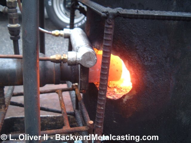
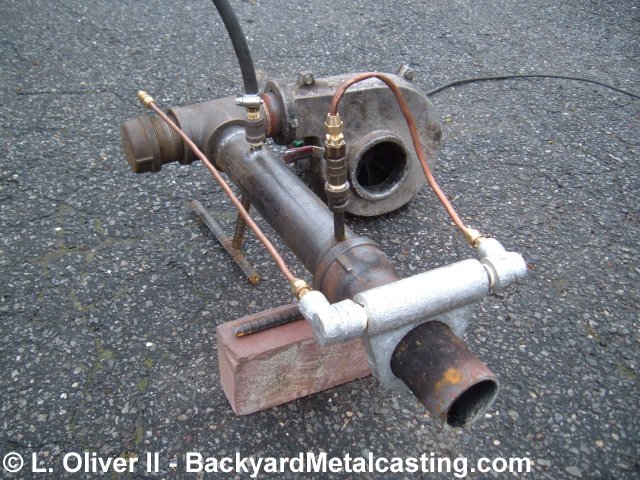
Notice how hot the flare pipe is, it's glowing orange. But notice also how the glowing stops at the thermal transfer ring. It is effectively absorbing the heat. Also notice the soot on the ring. While it's hot it's not hot enough to burn it off since oil absorbs the excess heat. This thermal transfer ring WORKED!! But unfortunetly it worked too well... The oil was heated so effectively that it vaporized and created pressure that pushed oil back up the fuel line preventing it from reaching the burner. So the flame was very erratic. Click photo for larger view
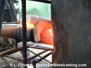
When the thermal transfer ring stopped the oil flow it began to really heat up since no oil was passing through and taking the heat away. So it actually began to melt and fall off. I think this idea would be much better with larger fuel lines and a larger oil "reservoir" inside the ring so the oil doesn't heat so fast that it vaporizes. I'm not very motivated to solve the problems with the design because I've learned that preheating the oil is not neccesary. With these lessons I've built a new burner with a bigger fuel line, no flare pipe and no oil preheater. I call it "The Brute." You can check it out melting iron! Technical details about The Brute are on the next page