Go to section: | Bracketry | The base part 1 | The base part 2 |
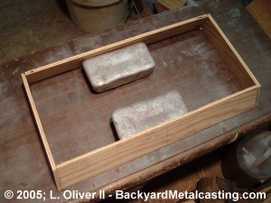
Here are the side panels being glued together. The base will have slanted sides so the wood was cut with angled ends. I'm using two aluminum ingots to support the wood until the glue dries.
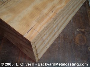
I decided that I want recessed mounting flanges for a more professional look. So after the top was glued in place the cutouts were laid out in four locations for the four flanges. I used a jigsaw to cut out the areas to become the recesses. It was then ready for the flange to be built in.
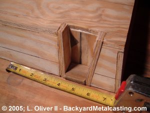
Here are the flange pieces installed and the glue is drying. It was important to design the flange area in a way to provide plenty of draft for molding. Once the glue on all four flanges is fully dry I'll begin laying out and gluing on the reinforcing pads and ribs which add thickness and rigidity to areas of the base that will have items bolted on or just need extra strength.
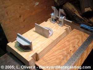
This photo illustrates some of the final layout work I was doing while triple checking the measurements. The original layout board is on the right with the T-square on it. You may notice the crosswise cut through the center of the top under the rear vice jaw. It was cut prior to gluing to relieve stresses that were causing the board to warp. It will be filled during the final stages of the pattern making.
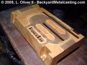
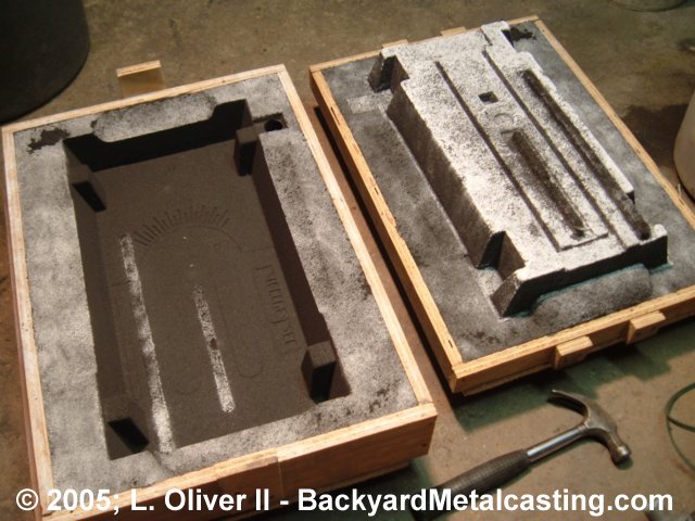
This is the top of the finished pattern ready for molding. The channel cut in the center is for the vice jaw guide and the one on the side is for the blade to pass through during a cut. Also notice the raised portions on the top. These are the areas that will be filed smooth for parts to be bolted onto or just provide a smooth sliding surface for the vice jaw. You can see that sections were cut out of the bottoms of the side panels. This was done for three reasons;
1) A more professional look.
2)The machine is supported just on the corners and mounting flanges.
3)To make it easy to lift the machine off the surface it's laying on.
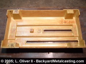
Here is the bottom of the pattern detailing where the reinforced areas are located. Notice that the areas surrounding the cutout channels are reinforced. All of the internal corners received fillets of wood filler and the outside corners were rounded off. All this to produce the smoothest sand mold. Wood filler was also used to fill any serious flaws in the wood. Finally three coats of polyurethane was applied, letting each coat completely dry before the next.
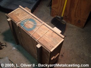
This is the heaviest sand mold I've made to this point. To roll this mold over I had to tie the halves together and turn the mold on it side then over again on the ground.
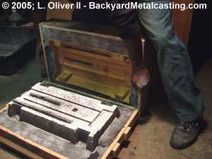
Here is the open sand mold. This is going to be the largest casting I've made up to this date. The flask's inner dimensions are is 25.5" long and 18" wide. The cope is 5" deep and to save weight the drag is only 2" deep (the casting is formed in the cope anyways). The flask required all but about 6 pounds worth of my molding sand (and I have probably a little over 200 pounds worth!).
Here is the cope (top half) on the left and the drag (bottom half) on the right. The biggest challenge with this mold was figuring out how to put the cope back on the drag (to close the mold) without the sand falling out. Sure I have ridges in the flask to help but when the cope weighs about 75 pounds they don't help as much as I'd like. The sand would often pull away from the long sides of the mold as I tilted the cope over. I solved the problem by pushing nails into the sand. The nails provided sufficient anchorage to keep the sand in place long enough for me to reinstall the cope. It took me about 4 tries before I got a successful mold. Click photo for larger view
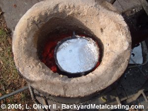
My current crucible can hold about 14 pounds of molten aluminum when filled to the brim (as it nearly is in the photo). If this casting ends up requiring more than 14 pounds of aluminum then that'll just be a cataclysmic delay which could completely derail the completion of this project! To ensure that the entire large mold filled completely before the metal solidified I let the metal "super heat" until it almost began to overheat. Time to pour the casting. Next page
Go to section: | Bracketry | The base part 1 | The base part 2 |