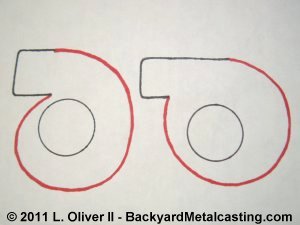
This diagram shows the two main styles of air blowers that are of use for a foundry or forge. On the left is the "spiral" or "scroll" type. These are based on an unraveling coil shape. On the right is what I call the "circular" type. They are based on a simple circle with an air outlet. The spiral design is said to be more efficient because the upper region has more space for air to collect, but the circular design is easier to draw on the wood to be cut out. The circular design is what I've used more than any other and it works great. It is the design of the blower being made in this example.

The first step is to determine the size of the blower you need/want and draw it's outline onto a piece of wood. Since the blower bodies I build are made in two parts (the halves bolt together) the blower outline is drawn twice. Notice that the outlines are mirror images of each other (reversed) so that when cut out the drawn lines come together on each half forming a matching joint. As you can see this will be a circular type blower. The outline is a simple circle with a corner added to it which will be the air's exit. Click photo for a larger view
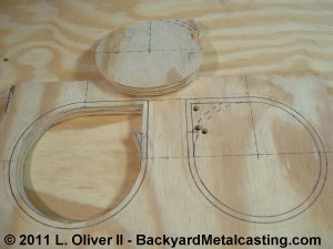
On the left the center has been cut out of one half following the inner layout line. Cutting the centers out first makes the process easier. I cut the halves out a jig saw, the saw blade is angled to provide for slightly tapered sides. This will provide what is called "draft" on the patterns so they slip out of the mold easily. The next cut will follow the outer layout line.

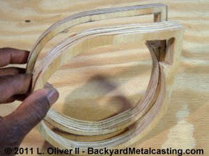
Here is one of the halves completely cut out. It is tapered inside and out. The second half will be cut out next. The holes drilled in the wood are for inserting the jigsaw blade to start a cut since it is hard to make one continuous cut with the sharp corners. Click photo for a larger view
Here are the halves cut out and loosely held together to illustrate how they match. The layout lines are on the inside facing each other for a matching joint.
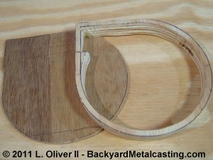
With the "body" portions cut out trace the outside of the body sections onto a sheet of thin (about 3/16") wood. These will become the outer faces of the blower.
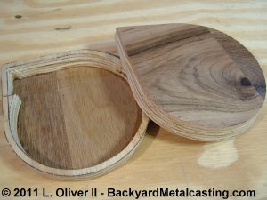
After sanding the inner surface of the blower body sections smooth, glue them onto the thin sections. It is now looking more like an air blower. Next the air outlet hole and nozzle will be formed.
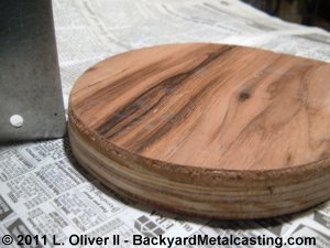
Just as a reminder, it is very important to make sure the patterns were cut out with draft. Notice the slight taper on the outside of the pattern. The inside has taper also (the inside has inward sloping sides like a food bowl). The pattern's parting line (where the mold splits) is the widest area.
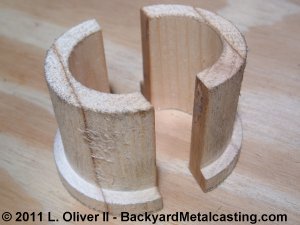
Here is the finished nozzle. There is one half for each half of the pattern. I made this on a lathe but they can be cut by hand also if necessary. The size is meant to fit over a 1" pipe and inside a 2" pipe, so the blower can work on either size burner.
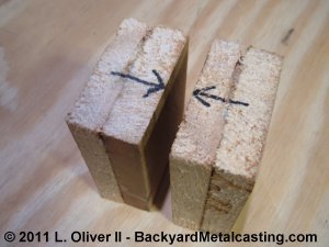
The nozzle is machined on a lathe from blocks of wood. Here I'm using pine. Notice how I've glued the blocks into groups of two so they'll be thick enough to form the nozzle. The two groups are then fastened together at the joint as indicated by the arrows. The next page shows how I formed the nozzle on the lathe. Continuation to part 2.